Master the conditions for spot welding! Optimal settings for both quality and efficiency
Yields do not improve easily, and even production efficiency drops. In such workplaces, spot welding settings are often fixed as a "guideline for the time being."
Even a slight adjustment to the current or welding force increases spatter and makes it difficult to achieve stable welding conditions.
In order to break this vicious cycle and maintain stable strength while producing, it is important to optimize the "three major conditions." This article explains how to do this.
Table of contents [hidden]
- 1.Understand the basics of spot welding
- 1.1.What is spot welding?
- 1.2.Three major conditions for spot welding
- 1.2.1.Howto set the welding current
- 1.2.2.welding force adjustment points
- 1.2.3.Theimportance of power-on time
- 1.3.Spotwelding nugget formation
- 1.3.1.Definition and Role of Nuggets
- 1.3.2.Factorsaffecting nugget diameter
- 2.Setting and optimizing welding conditions
- 2.1.Use the spot welding condition table
- 2.2.Selection of welding materials and electrodes
- 2.2.1.Types and properties of metals
- 2.2.2.Selectingelectrode materials
- 2.2.3.Types of electrode tip shapes
- 3.Summary
Understanding Spot Welding Basics
Here, based on the mechanism of spot welding (resistance welding), we will organize the interactions between the three major conditions - welding current, welding time, and welding force- and explain the entire process leading up to nugget formation in a systematic way.
What is spot welding?
"Spot welding" is a technique for joining metals in which metal plates are sandwiched between electrodes and a large current is passed through them to generate heat locally, melting and joining them. For more information about this welding technique, please refer to the article below.
The three major conditions for spot welding
The three main conditions for spot welding (resistance welding) are "welding current (I)", "current application time (t)", and "welding force (F)".
These conditions determine the intensity and spread of the heat generated, which in turn determines the size of the nugget and the state of penetration.
If anyone of theseis outside the appropriate range, defects such as increased spatter, incomplete melting, and peeling will occur.
How to set the welding current
<Current value guideline and calculation method>
To find an estimate of the current for each plate thickness, the formula "I=k×t^0.5" (I:current,k:coefficient,t:plate thickness) is often used.
This formula is a practical and effective method that takes into account the capacity of the welding machine and the lifespan of the electrodes so that the required current does not increase suddenly even when the thickness of the workpiece to be welded changes.
<Risks of overcurrent and appropriate settings>
If the current is too strong, spatter (metal scattering) will occur, and the molten metal will adhere to the electrode, shortening its lifespan. To determine the appropriate current value, it is effective to check the nugget diameter and amount of spatter while gradually increasing the current.
Defects caused by overcurrent can be prevented by setting the upper limit at an additional 1kA above the current value that satisfies the minimum nugget diameter specified in the JIS standard.
welding force adjustment points
If welding force is insufficient, spatter will increase and the surface will be more likely to burn.
Conversely, if welding force is too strong, the contact resistance will decrease, the amount of heat will decrease, the required nugget diameter and penetration will not be sufficient, and the welding strength will not be stable.
When observing the fracture surface, if you see "double rings with a blue burnt outer edge and an unmelted center," this is a sign of welding force.
Another thing to keep in mind is that the set value and the actual welding force may not always match. With air guns and servo guns, there are cases where a set value of5.0kNis actually applied, but only 4.5kN is actuallywelding force. The conditions can be met by measuring and recording welding force with welding force and feeding back the actual value.
The importance of power-on time
When setting the power supply time, you need to be careful of the frequency at the border of the Fuji River in Shizuoka Prefecture.
Eastern50HzIn the region1Due to the long cycle time,60HzFor the region setting,×1.2This can be easily calculated by converting it into
Reducing the energization time reduces spatter and shortens the cycle time, but misalignment or differences in plate thickness increase the risk of non-melting, so it is important to maintain the appropriate range. Check the following three points as a guide.
The nugget diameter is JIS lower limit + 0.5 mm or more
The amount of spatter is within the allowable range
The electrode temperature is not on an upward trend.
When reviewing the conditions, adjust them in the order of "current → welding force → current duration," and then fine-tune the current duration last, and you will be able to approach the optimum conditions without any hesitation.
Spot welding nugget formation
The nugget is the core of quality assessment in spot welding. Even if the three major conditions are met, the weld strength will not be achieved unless the nugget diameter, shape, and internal structure meet the standard values. From here, we will explain in detail about nuggets, how they are made, and how to examine them.
Definition and role of nuggets
A nugget is a part of a spot weld where the metal melts and solidifies, firmly joining the welded workpieces together.
This is the most important part that supports the strength of the welded part, and when formed properly, it creates a joint that is harder and stronger than the original metals.
To check the quality of welding, the Japanese Industrial Standards (JIS) and other standards stipulate the size (diameter) of the nugget and the shape (fracture surface shape) of the nugget when the welded workpiece is peeled off.

Factors affecting nugget diameter
Nugget diameter is determined by several factors, including plate thickness, electrode tip diameter, current, welding force, and current application time. Over long-term operation, electrode wear inevitably leads to an increase in tip diameter. By combining periodic dressing and the automatic current tracking function(constant current function), nugget diametervariationcan be reduced.
[Examples of differences due to materials]
・Aluminum: Due to its high thermal conductivity, heat tends to dissipate easily even when the current is increased, so the current tends to flow for a longer time.
- High-tensile steel: It generates heat easily, and if the current is increased too much, it is prone to explosion, so adjusting welding force is key.
Setting and optimizing welding conditions
In spot welding, it is essential to set conditions that match the material's characteristics and plate thickness.
By setting standard values based on the condition table and selecting the correct material and tip shape, stable quality and efficient production can be achieved.
Utilizing spot welding condition tables
The welding condition table shows the "approximate setting values to try first" according to the plate thickness and type.
What are the RWMA's recommended conditions?
The Recommended Conditions Table published by the Resistance Welding Machine Manufacturers Association (RWMA) is a common example of conditions that many manufacturers first refer to.
The vertical columns of the table show plate thickness, and the horizontal axis shows welding current, current cycle, and electrode welding force, and by setting these intermediate conditions (Class B) as the starting value during the prototype stage, you can prevent major rework. Please note that the heat input efficiency differs depending on whether the power source is inverter type or single-phase AC type, so the results will vary even with the same current value.
board | electrode | most | most | Best conditions (Class A) | Intermediate condition (Class B) | Normal conditions (Class C) | |||||||
m | m | time | Canada | electric | time | Canada | electric | time | Canada | electric | |||
0.4 | 3.2 | 12 | 8 | 10 | 4 | 120 | 5400 | 8 | 75 | 4400 | 20 | 40 | 3500 |
0.5 | 3.5 | 12 | 9 | 11 | 5 | 135 | 6000 | 10 | 90 | 5000 | 23 | 45 | 3900 |
0.6 | 4.0 | 12 | 10 | 11 | 6 | 150 | 6600 | 12 | 100 | 5500 | 26 | 50 | 4300 |
0.8 | 4.5 | 12 | 12 | 11 | 8 | 175 | 8000 | 16 | 120 | 6400 | 32 | 70 | 5000 |
1.0 | 5.0 | 12 | 18 | 12 | 10 | 220 | 9000 | 20 | 150 | 7200 | 36 | 85 | 5600 |
1.2 | 5.5 | 12 | 20 | 14 | 12 | 275 | 10000 | 23 | 175 | 8000 | 42 | 100 | 6100 |
1.4 | 6.0 | 12 | 24 | 15 | 14 | 320 | 10800 | 26 | 200 | 8600 | 46 | 120 | 6600 |
1.6 | 6.3 | 13 | 27 | 16 | 16 | 370 | 11600 | 30 | 230 | 9200 | 52 | 135 | 7100 |
1.8 | 6.7 | 16 | 31 | 17 | 18 | 430 | 12500 | 33 | 260 | 9800 | 54 | 155 | 7600 |
2.0 | 7.0 | 16 | 35 | 18 | 20 | 480 | 13200 | 38 | 300 | 10400 | 60 | 175 | 8000 |
2.3 | 7.6 | 16 | 40 | 20 | 24 | 570 | 14400 | 43 | 330 | 11000 | 65 | 200 | 8600 |
2.8 | 8.5 | 16 | 45 | 21 | 28 | 700 | 16000 | 52 | 430 | 12400 | 76 | 230 | 9500 |
3.2 | 9.0 | 16 | 50 | 22 | 32 | 820 | 17400 | 60 | 480 | 13200 | 84 | 285 | 10200 |
Selection of welding materials and electrodes
We will organize the selection criteria that fundamentally support the condition setting from three perspectives: material properties, electrode material, and tip shape.
Metal types and properties
Aluminum: High thermal conductivity and easy cooling, so in addition to increasing the current, the current flow time can also be set in detail.
Copper: Low resistance and little spatter, but spatter is likely to occur if welding force is insufficient.
Titanium: It has an active surface, and when the oxide film becomes thick, it inhibits electrical conduction, so high welding force and an inert atmosphere are required.
How to choose electrode materials
RWMAelectrode material classes are organized by the balance between conductivity and hardness.
The higher the surface hardness, the slower the electrode wears, but the heat generated increases as the conductivity decreases, so the cooling design must be strengthened to maintain welding quality.
[Electrode selection example]
High-tensile steel: High-strength steel is selected as a high priority due to rapid electrode wear.
Aluminum: Since insufficient heat generation can be a problem, conductivity is prioritized (radius type is common)
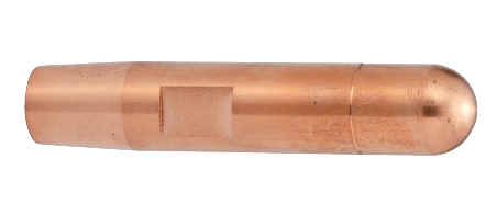
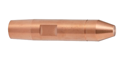
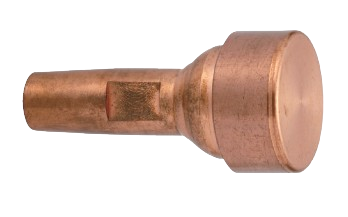
Types of electrode tip shapes
"Form": The form and name of the electrode tip varies depending on the manufacturer.
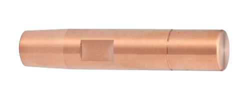
"F": Flat type
Flat shape that minimizes dents on the welding workpiece
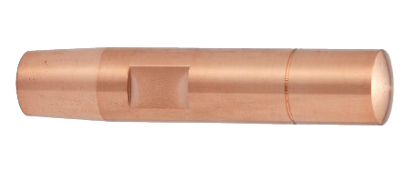
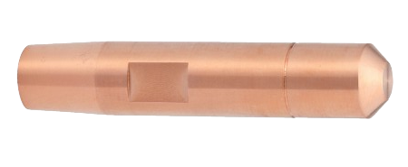
"R": Radius type
A gentle dome shape in which the welding surface bites into the base material as current flows.
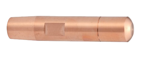
"D": Dome shape
Compared to a radius, the dome has a sharper angle, resulting in a smaller contact area and excellent current concentration.
"CF": Conical trapezoid
Conical tip with flat welding surface
"CR": Conical trapezoid radius
The conical tip has a gentle dome-shaped weld surface
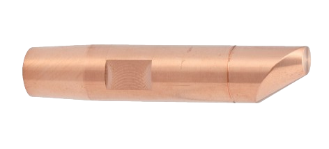
"E": Eccentric type
A shape that increases accessibility when you want to hit the very back of a workpiece, such as when welding.
"P": Point type
A shape often used where the space for welding is narrow
Swivel Tip
The contact surface is flat and the neck moves smoothly, adapting to the workpiece.
summary
In this article, we have explained the following about setting conditions for spot welding.
・Three major conditions for spot welding
・Spot welding nuggets
・Optimization of welding conditions
・Selection of welding materials and electrodes
If you are having trouble setting spot welding conditions, selecting electrodes, or selecting a welding machine, please contact Daido Kogyo!